compendio de circuitos lógicos que pueden implementarse en las danzas compuertas.
acerca de
los circuitos lógicos en este compendio están descritos en verilog, un lenguaje descriptor de hardware. esto con la idea de estandarizarlos, de facilitar simularlos e implementarlos en otros materiales, y de indicar su cualidad de red abstracta.
cada circuito indica un número de participantes que varía entre dos opciones. el número menor está calculado como el número de entradas más el número de compuertas. el otro número suma también el número de salidas del circuito completo, que de otra forma serían realizadas por alguna(s) de las compuertas.
utilizamos el lenguaje a nivel de compuertas lógicas solamente: cada compuerta se expresa como una función (and(), not(), or(), nor(), nand(), etc) donde el primer argumento es el nombre de la salida de la compuerta, y el o los otros argumentos son los nombres de las entradas.
específicamente, los circuitos están clasificados como los que usan compuertas habituales, o los que están construidos utilizando únicamente compuertas nor.
este es un compendio de circuitos lógicos que pueden implementarse en las danzas compuertas.
multiplicador de 1 bit
circuito que multiplica a dos números de 1 bit y da el resultado en 1 bit.
multiplicador de 1 bit con compuertas habituales (3 o 4 participantes)
// multiplicador construido con compuertas habituales
// entradas (2): a,b
// salidas (1): r (resultado)
// compuertas (1): 1 de 2 entradas

module multiplicador( a, b, r);

input wire a, b;
output wire r;

and C1(r, a, b);

endmodule
multiplicador de 1 bit con nor (5 o 6 participantes)
// multiplicador construido con nor's
// entradas (2): a,b
// salidas (1): r (resultado)
// compuertas (3): 2 de 1 y 1 de 2 entradas

module multiplicador( a, b, r);

input wire a, b;
output wire r;
wire p1,p2;

// negadas
nor C1(p1, a);
nor C2(p2, b);

// resultado
nor C3(r, p1, p2);

endmodule
contadores
circuitos que incrementan 1 al número binario colocado en la entrada, con el mismo número de bits a la entrada que a la salida.
si la salida se "conecta" a la entrada, entonces con cada paso se obtiene el
número siguiente en la secuencia, es decir se "cuenta".
al llegar al último número, se regresa a 0.
contador de 2 bits con compuertas habituales (4 o 6 participantes)
// contador de 2 bits con compuertas habituales
// entradas (2): a, b
// salidas (2):  x, y
// compuertas (2): 1 de 1 y 1 de 2 entradas

module contador(a, b, x, y);

input wire a,b;
output wire x,y;

not C1(y, b);
xor C2(x, a,b);

endmodule
contador de 2 bits con nor (7 o 9 participantes)
// contador de 2 bits con nor
// entradas (2): a, b
// salidas (2):  x, y
// compuertas (5): 2 de 1 y 3 de 2 entradas

module contador(a, b, x, y);

input wire a,b;
output wire x,y;
wire p1, p2, p3;

// negaciones
nor C1(y, b);
nor C2(p1, a);

// para x
nor C3(p2, a,b);
nor C4(p3, y,p1);
nor C5(x, p2,p3);

endmodule
contador de 3 bits con compuertas habituales (11 o 14 participantes)
// contador de 3 bits con compuertas habituales
// entradas (3): a, b, c
// salidas (3): x, y, z
// compuertas (8): 3 de 1, 3 de 2, 2 de 3 entradas

module contador(a, b, c,  x, y, z);

input wire a,b,c;
output wire x,y,z;
wire p1, p2, p3, p4, p5;

// negaciones
not C1(p1, a);
not C2(p2, b);
not C3(z, c);

// para y
xor C2(y, a,b);

// para x
and(p3,  p1, b, c)
and(p4,  a, p2)
and(p5,  a, z)
or(x,  p3, p4, p5)

endmodule
contador de 3 bits con nor (13 o 16 participantes)
// contador de 3 bits con nor
// entradas (3): a, b, c
// salidas (3):  x, y, z
// compuertas (10): 3 de 1, 4 de 2, 3 de 3 entradas

module contador(a, b, c,  x, y, z);

input wire a,b,c;
output wire x,y,z;
wire p1, p2, p3, p4, p5, p6, p7;

// negaciones
nor C1(p1, a);
nor C2(p2, b);
nor C3(z, c);

// para y
nor C4(p3, b,c);
nor C5(p4, p2,z);
nor C6(y, p3,p4);

// para x
nor C7(p5, a,b);
nor C8(p6, p1, p2, z);
nor C9(p7, a, p2, c);
nor C10(x, p5, p6, p7);

endmodule
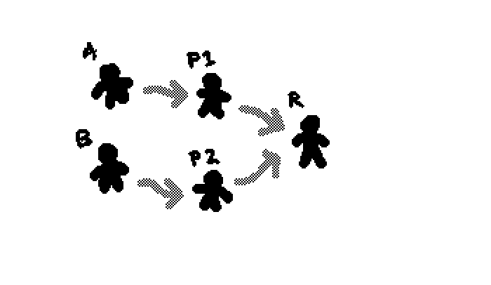
half adder
circuito que suma dos bits y da el resultado en dos bits (resultado y *carry*)
half adder con compuertas habituales (4 o 6 participantes)
// half adder construido con compuertas habituales
// entradas (2): a,b
// salidas (2): r, c (resultado, carry)
// compuertas (2): 2 de 2 entradas

module halfadder( a, b, r, c);

input wire a, b;
output wire r,c;

// carry
and C1(c, a, b);

// resultado
xor C2(r, a, b);

endmodule
half adder usando nor (7 o 9 participantes)
// half adder construido usando nor's
// entradas (2): a,b
// salidas (2): r, c (resultado, carry)
// compuertas (5): 2 de 1 y 3 de 2 entradas

module halfadder( a, b, r, c);

input wire a, b;
output wire r,c;
wire p1,p2,p3;

// negadas
nor C1(p1, a);
nor C2(p2, b);

// carry
nor C3(c, p1, p2);

// resultado
nor C4(p3, a, b);
nor C5(r, c, p3);

endmodule
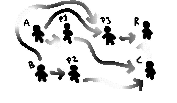
full adder
circuito que suma tres bits y da el resultado en dos bits (resultado y *carry*).
full adder con compuertas habituales (14 o 16 participantes)
// full adder construido con compuertas habituales
// entradas (3): a, b, c
// salidas (2): carry, r (resultado)
// compuertas (11): 2 de 1 y 9 de 2 entradas

module fulladder( a, b, c, r, carry);

input wire a, b, c;
output wire r, carry;
wire p1, p2, p3, p4, p5, p6, p7, p8, p9;

// negadas
not C1(p1, a);
not C2(p3, p2);

// diferencias b,c
xor C3(p2, b, c);
or C4(p4, b, c);
and C5(p5, b, c);

// armado de resultado
and C6(p6,  p1, p2);
and C7(p7,  a, p3);
or C8(r, 	 p6, p7);

// armado de carry
and C9(p8,  p1, p5);
and C10(p9,  a, p4);
or C11(carry,   p8, p9);

endmodule
full adder usando nor (15 o 17 participantes)
computadora no(r)palera de coloring computers
// full adder construido usando nor's
// entradas (3): a, b, c
// salidas (2): carry, r (resultado)
// compuertas (12): 3 de 1, 3 de 2, 4 de 3 y 1 de 4 entradas

module fulladder( a, b, c, r, carry);

input wire a, b, c;
output wire r, carry;
wire p1, p2, p3, p4, p5, p6, p7, p8, p9, p10;

// negadas
nor C1(p1, a);
nor C2(p2, b);
nor C3(p3, c);

// pa'l carry
nor C4(p4, a, b);
nor C5(p5, a, c);
nor C6(p6, b, c);

// pa resultado
nor C7(p7, a, b , c);
nor C8(p8, p1, b, p3);
nor C9(p9, a, p2, p3);
nor C10(p10, p1, p2, c);

// salidas
nor C11(carry, p4, p5, p6);
nor C12(r, p7, p8, p9, p10);

endmodule
7-segment display logic
may this serve as a reference for non-electronic, human-scale, very-slow implementations of digital circuits that use a 7-segment display as an output.
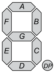
hex-digit to seven-segment table:
    a   b   c   d   e   f   g
0   1   1   1   1   1   1   0
1   0   1   1   0   0   0   0
2   1   1   0   1   1   0   1
3   1   1   1   1   0   0   1
4   0   1   1   0   0   1   1
5   1   0   1   1   0   1   1
6   1   0   1   1   1   1   1
7   1   1   1   0   0   0   0
8   1   1   1   1   1   1   1
9   1   1   1   1   0   1   1
A   1   1   1   0   1   1   1
b   0   0   1   1   1   1   1
C   1   0   0   1   1   1   0
d   0   1   1   1   1   0   1
E   1   0   0   1   1   1   1
F   1   0   0   0   1   1   1
hexadecimal decoder
different gate-level implementations of a 4-bit to 7-segment display hexadecimal decoder: the input is a 4-bit binary number, and the output is the display showing the corresponding hexadecimal digit.
- straightforward version (S)
- simplified version (K)
- simplified version in NOR
- simple-simplified version (Z)
comparison of number of gates:
             S   K   Z
NOT          4   4   4
2-input OR   0   1  29
3-input OR   0  10   0
4-input OR  15  10   0
2-input AND  0   0   3
3-input AND  0   3   4
4-input AND  3   3   2
5-input AND  2   1   0
6-input AND  2   0   0

total       26  32  42
in cases S and K, the gates AND,OR can be replaced with NOR.
straightforward version
this circuit uses a complete "product of maxterms" for each of the segments.
the maxterms correspond to the numbers that turn off that specific segment.
// 4-bit hexadecimal to 7-segment decoder with traditional gates
module hex_to_7seg( b3, b2, b1, b0, a, b, c, d, e, f, g);

input wire b3, b2, b1, b0; // 4 bits as input
output wire a, b, c, d, e, f, g; // 7 segments as output

// inversions:
wire n3,n2,n1,n0;
// maxterms:
wire orF, orE, orD, orC, orB, orA, or9, or7, or6, or5, or4, or3, or2, or1, or0;

// inversions:
not G00( n0, b0);
not G01( n1, b1);
not G02( n2, b2);
not G03( n3, b3);

// maxterms:
or G04( or0, b3, b2, b1, b0); // 0b0000, 0
or G05( or1, b3, b2, b1, n0); // 0b0001, 1
or G06( or2, b3, b2, n1, b0); // 0b0010, 2
or G07( or3, b3, b2, n1, n0); // 0b0011, 3
or G08( or4, b3, n2, b1, b0); // 0b0100, 4
or G09( or5, b3, n2, b1, n0); // 0b0101, 5
or G10( or6, b3, n2, n1, b0); // 0b0110, 6
or G11( or7, b3, n2, n1, n0); // 0b0111, 7

or G12( or9, n3, b2, b1, n0); // 0b1001, 9
or G13( orA, n3, b2, n1, b0); // 0b1010, A
or G14( orB, n3, b2, n1, n0); // 0b1011, B
or G15( orC, n3, n2, b1, b0); // 0b1100, C
or G16( orD, n3, n2, b1, n0); // 0b1101, D
or G17( orE, n3, n2, n1, b0); // 0b1110, E
or G18( orF, n3, n2, n1, n0); // 0b1111, F

// each segment (see table above)
and G19( a, or1, or4, orB, orD);
and G20( b, or5, or6, orB, orC, orE, orF);
and G21( c, or2, orC, orE, orF);
and G22( d, or1, or4, or7, orA, orF);
and G23( e, or1, or3, or4, or5, or7, or9);
and G24( f, or1, or2, or3, or7, orD);
and G25( g, or0, or1, or7, orC);

endmodule
simplified version
this first simplification consists in reducing the number of inputs in the maxterms.
the general architecture stays the same: one level of ORs, and one level of ANDs.
// 4-bit hexadecimal to 7-segment decoder with traditional gates, "simplified"
module hex_to_7seg( b3, b2, b1, b0, a, b, c, d, e, f, g);

input wire b3, b2, b1, b0; // 4 bits as input
output wire a, b, c, d, e, f, g; // 7 segments as output

// inversions:
wire n3,n2,n1,n0;
// maxterms:
wire orD, orC, orB, orA, or9, or7, or5, or4, or2, or1;

// others:
wire or111X, or11X0, or1X11, orX110, orX111, or010X, or00X1, or001X, or0X11, or000X;
wire or0XX1;

// inversions:
not G00( n0, b0);
not G01( n1, b1);
not G02( n2, b2);
not G03( n3, b3);

// maxterms:
// we keep the maxterms: 1, 2, 4, 5, 7, 9, A, B, C, D
or G04( or1, b3, b2, b1, n0); // 0b0001, 1
or G05( or2, b3, b2, n1, b0); // 0b0010, 2
or G06( or4, b3, n2, b1, b0); // 0b0100, 4
or G07( or5, b3, n2, b1, n0); // 0b0101, 5
or G08( or7, b3, n2, n1, n0); // 0b0111, 7
or G09( or9, n3, b2, b1, n0); // 0b1001, 9
or G10( orA, n3, b2, n1, b0); // 0b1010, A
or G11( orB, n3, b2, n1, n0); // 0b1011, B
or G12( orC, n3, n2, b1, b0); // 0b1100, C
or G13( orD, n3, n2, b1, n0); // 0b1101, D

// 3-input ORs:
or G14(or111X, n3, n2, n1);
or G15(or11X0, n3, n2, b0);
or G16(or1X11, n3, n1, n0);
or G17(orX110, n2, n1, b0);
or G18(orX111, n2, n1, n0);
or G19(or010X, b3, n2, b1);
or G20(or00X1, b3, b2, n0);
or G21(or001X, b3, b2, n1);
or G22(or0X11, b3, n1, n0);
or G23(or000X, b3, b2, b1);

// 2-input OR:
or G24(or0XX1, b3, n0);

// each segment
and G25( a, or1, or4, orB, orD); // 4-inputs
and G26( b, or111X, or11X0, or1X11, orX110, or5); // 5-inputs
and G27( c, or111X, or11X0, or2); // 3-inputs
and G28( d, orX111, or1, or4, orA); // 4-inputs
and G29( e, or0XX1, or010X, or9); // 3-inputs
and G30( f, or00X1, or001X, or0X11, orD); // 4-inputs
and G31( g, or000X, or7, orC); // 3-inputs

endmodule
simplified version, with NOR gates and cleaned up labels
this is the same circuit as above, but replacing the AND,OR gates with NOR gates (thanks to it being a "two-level product of maxterms" ciruit).
here the gates and their output wires are labelled GXX and gXX respectively, using octal numbering.
// 4-bit hexadecimal to 7-segment decoder with NOR gates
// "cleaned up" wire names
module hex_to_7seg( b3, b2, b1, b0, a, b, c, d, e, f, g);

input wire b3, b2, b1, b0; // 4 bits as input
output wire a, b, c, d, e, f, g; // 7 segments as output

wire g00, g01, g02, g03, g04, g05, g06, g07;
wire g10, g11, g12, g13, g14, g15, g16, g17;
wire g20, g21, g22, g23, g24, g25, g26, g27;
wire g30, g31, g32, g33, g34, g35, g36, g37;

// inversions:
not G00( g00, b0);
not G01( g01, b1);
not G02( g02, b2);
not G03( g03, b3);

// maxterms:
// we keep the maxterms: 1, 2, 4, 5, 7, 9, A, B, C, D
nor G04( g04, b3, b2, b1, g00); // 0b0001, 1
nor G05( g05, b3, b2, g01, b0); // 0b0010, 2
nor G06( g06, b3, g02, b1, b0); // 0b0100, 4
nor G07( g07, b3, g02, b1, g00); // 0b0101, 5
nor G10( g10, b3, g02, g01, g00); // 0b0111, 7
nor G11( g11, g03, b2, b1, g00); // 0b1001, 9
nor G12( g12, g03, b2, g01, b0); // 0b1010, A
nor G13( g13, g03, b2, g01, g00); // 0b1011, B
nor G14( g14, g03, g02, b1, b0); // 0b1100, C
nor G15( g15, g03, g02, b1, g00); // 0b1101, D

// 3-input:
nor G16(g16, g03, g02, g01);
nor G17(g17, g03, g02, b0);
nor G20(g20, g03, g01, g00);
nor G21(g21, g02, g01, b0);
nor G22(g22, g02, g01, g00);
nor G23(g23, b3, g02, b1);
nor G24(g24, b3, b2, g00);
nor G25(g25, b3, b2, g01);
nor G26(g26, b3, g01, g00);
nor G27(g27, b3, b2, b1);

// 2-input:
nor G30(g30, b3, g00);

// each segment
nor G31( g31, g04, g06, g13, g15); // 4-inputs
nor G32( g32, g16, g17, g20, g21, g07); // 5-inputs
nor G33( g33, g16, g17, g05); // 3-inputs
nor G34( g34, g22, g04, g06, g12); // 4-inputs
nor G35( g35, g30, g23, g11); // 3-inputs
nor G36( g36, g24, g25, g26, g15); // 4-inputs
nor G37( g37, g27, g10, g14); // 3-inputs

assign a = g31;
assign b = g32;
assign c = g33;
assign d = g34;
assign e = g35;
assign f = g36;
assign g = g37;
simple-simplified version, with "normal" gates
in this circuit, repeated OR operations were "abbreviated": 4-input OR gates were replaced by 3 2-input OR gates, taking advantage of the fact that many of those 2-input ORs are common and can be reused.
here the transformation to NOR gates is not as straightforward: each OR that is an input for another OR, has to be inverted (adding a NOT) before being able to convert OR, AND to NORs.
this circuit is implemented as the 4-bits to 7-segment display hexadecimal decoder in the coloring computers.
// 4-bit hexadecimal to 7-segment decoder with traditional gates, "simplified"
module hex_to_7seg( b3, b2, b1, b0, a, b, c, d, e, f, g);

input wire b3, b2, b1, b0; // 4 bits as input
output wire a, b, c, d, e, f, g; // 7 segments as output

// inversions:
wire n3,n2,n1,n0;
// maxterms:
wire orD, orC, orB, orA, or9, or7, or5, or4, or2, or1;

// others:
wire or111X, or11X0, or1X11, orX110, orX111, or010X, or00X1, or001X, or0X11, or000X;
wire or0XX1;
wire orXX00, orXX01, orXX10, orXX11, or00XX, or01XX, or10XX, or11XX;

wire and_or1or4, and_or111Xor11X0;

// inversions (4 gates)
not N00( n0, b0);
not N01( n1, b1);
not N02( n2, b2);
not N03( n3, b3);

// pairs of bits (9 gates)
or P00( orXX00, b1, b0); // ++
or P01( orXX01, b1, n0); // ++++
or P02( orXX10, n1, b0); // +++
or P03( orXX11, n1, n0); // ++++
or P04( or00XX, b3, b2); // +++
or P05( or01XX, b3, n2); // ++++
or P06( or10XX, n3, b2); // +++
or P07( or11XX, n3, n2); // ++++
// 2-input OR:
or P08( or0XX1, b3, n0); // ++

// was-3-input ORs (10 gates)
or T00(or111X, or11XX, n1); //n3, n2, n1;
or T01(or11X0, or11XX, b0); //n3, n2, b0;
or T02(or1X11, orXX11, n3); //n3, n1, n0;
or T03(orX110, orXX10, n2); //n2, n1, b0;
or T04(orX111, orXX11, n2); //n2, n1, n0;
or T05(or010X, or01XX, b1); //b3, n2, b1;
or T06(or00X1, or0XX1, b2 ); //b3, b2, n0;
or T07(or001X, or00XX, n1 ); //b3, b2, n1;
or T08(or0X11, or0XX1, n1 ); //b3, n1, n0;
or T09(or000X, or00XX, b1 ); //b3, b2, b1;

// maxterms: (10 gates, 2-input)
// we keep the maxterms: 1, 2, 4, 5, 7, 9, A, B, C, D
or M1( or1, or00XX, orXX01); // 0b0001, 1
or M2( or2, or00XX, orXX10); // 0b0010, 2
or M4( or4, or01XX, orXX00); // 0b0100, 4
or M5( or5, or01XX, orXX01); // 0b0101, 5
or M7( or7, or01XX, orXX11); // 0b0111, 7
or M9( or9, or10XX, orXX01); // 0b1001, 9
or MA( orA, or10XX, orXX10); // 0b1010, A
or MB( orB, or10XX, orXX11); // 0b1011, B
or MC( orC, or11XX, orXX00); // 0b1100, C
or MD( orD, or11XX, orXX01); // 0b1101, D

// helper ANDs (2 gates, 2-inputs)
and A01( and_or1or4, or1, or4);
and A02( and_or111Xor11X0, or111X, or11X0);

// each segment  (7 gates)
and Sa( a, and_or1or4, orB, orD); // 3-inputs
and Sb( b, and_or111Xor11X0, or1X11, orX110, or5); // 4-inputs
and Sc( c, and_or111Xor11X0, or2); // 2-inputs
and Sd( d, and_or1or4, orX111, orA); // 3-inputs
and Se( e, or0XX1, or010X, or9); // 3-inputs
and Sf( f, or00X1, or001X, or0X11, orD); // 4-inputs
and Sg( g, or000X, or7, orC); // 3-inputs

endmodule
bouncing ball
see bouncing ball logic.